Description
Rustrol® Gradient Control Systems (GCS)*
The Rustrol® Gradient Control Systems (GCS)* provide for a reliable, maintenance-free grounding/safety grid (i.e. Mat, Cable, or Ribbon), capable of reducing and/or preventing the potential shock hazard to personnel and equipment, typically associated with exposure to “Step & Touch” voltages.
IEEE Standard 80 (latest revision) details acceptable “Step & Touch” voltage criteria and provides the safe limits of potential differences that can exist within independent structures exposed to electric shock hazards. Consideration must be provided for the physical phenomena by which AC, AC Power Systems and Lightning can effect a typical metallic structure such as pipelines.
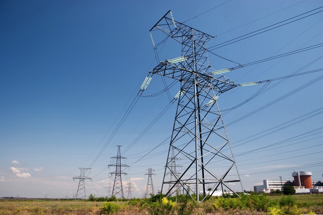
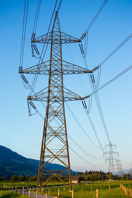
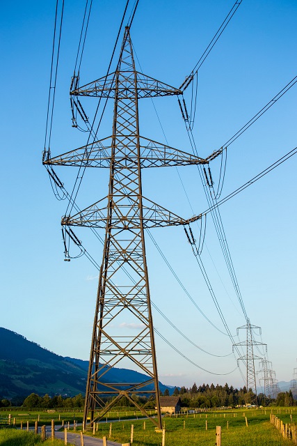
AC mitigation is often a concern for pipelines that are in the vicinity of Electrical Power Transmission Corridors. The metallic pipeline typically is exposed to induced AC voltage; hence, the pipeline may retain high AC voltage potentials in excess of acceptable “Step & Touch” potentials, as stated within industry standards; CAN/CSA – C22.3, No. 6-M91, IEEE 80, IEEE C2 and NACE International Standard Practice SP0177.
Product Brochures
Rustrol® Gradient Control Systems (GCS)
Rustrol® Gradient Control System – Mat™
Rustrol® Gradient Control System-MAT Typical Installation for Step & Touch
Rustrol® Gradient Control System-MAT Typical Installation for AC Mitigation
Rustrol® Gradient Control System-Zinc Ribbon Typical Installation for AC Mitigation
Rustrol® Gradient Control System-Copper Cable Typical Installation for AC Mitigation
Rustrol® Gradient Control Systems (GCS)*
The Rustrol® Gradient Control Systems (GCS)* are provided in configurations as deemed necessary for unique applications: Gradient Control Mat (GCS-M), and/or Gradient Control Copper Cable/Zinc Ribbon (GCS-CC; GCS-ZR), which are typically connected to the primary structure (i.e. pipeline) in series arrangement through a Rustrol® Cathodic Isolator®, Model: SSP or the Rustrol® DC-Decoupler™, Model: DCD.
The Rustrol® Gradient Control Systems (GCS)* provide a conducting path to the electrical utilities grounding network, utilizing the Rustrol®, Model: SSP or DCD (i.e. DC-Decoupling Device). The Solid State DC-Decoupler Device maintains a high resistance to low-voltage DC, ensuring cathodic protection design criteria will not be compromised for the primary structure (i.e. pipeline). In addition, the Rustrol®, Model: SSP or DCD (i.e. DC-Decoupling Device), will maintain electrical characteristics of low impedance to AC, hence free to conduct AC induced voltages, AC Fault Currents and/or lightning exposure that may occur on the pipeline.
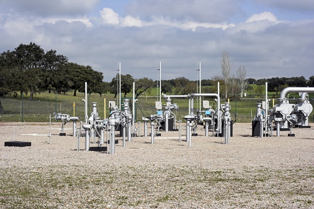
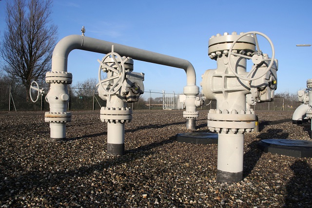
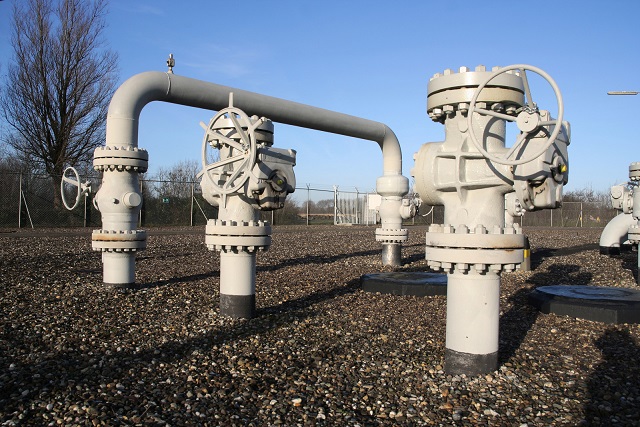
The Rustrol® Gradient Control System – Mat™ (GCS-M)* is utilized primarily to limit shock risks caused by localized “Step & Touch” voltage potentials, that often occur within Valve Stations, Electrical Substations and enroute of pipelines at Test Station locations. In accordance with NACE International Standard SP0177 (latest revision), to reduce electrical “Step & Touch” voltages in areas where the general public and/or operating personnel may come in contact with a primary structure (i.e. pipeline) that is exposed to hazardous potentials, gradient control mats should be considered.
The Rustrol® Gradient Control System – Mat™ (GCS-M)* is available in three (3) typical construction materials as follows:
- Hot Dipped Galvanized Steel Mat,
Specifications: Approximately 1200mm x 1800mm (4′.0″ x 6′.0″), Grid: 150mm x 150mm (6″.0 x 6″.0) Welded Mesh, Mesh Thickness: 6.35mm (1/4″).
Order Code: Part No.GCS-M-64663-GS-3 (Typical Photograph) - Copper Clad Steel Mat,
Specifications: Approximately 1200mm x 1800mm (4′.0″ x 6′.0″), Grid: 150mm x 150mm (6″.0 x 6″.0) Welded Mesh, Mesh Thickness: 4.10mm (1/6″).
Order Code: Part No.GCS-M-64663-CC-2 (Typical Photograph) - Solid Copper Mat,
Specifications: Approximately 1200mm x 1800mm (4′.0″ x 6′.0″), Grid: 150mm x 150mm (6″.0 x 6″.0) Welded Mesh, Mesh Thickness: 4.10mm (1/6″).
Example of Order Code: Part No.GCS-M-64663-SC-2 (Typical Photograph) - Alternative Sizes Available, Refer To Gradient Control System – Mat™ Brochure.
- Custom Gradient Mat Configuration available on request
NACE International Standard SP0177 (latest revision) provides the following guidelines to improve the efficiency of the Gradient Control System-Mat™ (GCS-M):
“A bed of clean, well-drained gravel can reduce the shock hazard associated with touch-and-step voltages…The thickness of the bed should be no less than 76 mm (3.0″). Gravel should be minimum of 13 mm (0.50″) in diameter. The hazardous of step voltages at the edge of a mat may be mitigated by extending the gravel beyond the perimeter of the ground mat.”
A typical installation utilizing a Rustrol® DC-Decoupler™ Model: DCD-ATEX-DT in conjunction with a Gradient Control System – Mat™ (GCS-M) is provided outlining methods to reduce AC “Step & Touch” potentials to be within acceptable levels per ICCC Drawing No. DCD-9A, Gradient Control System – Mat ™.
The Rustrol® Gradient Control System – Copper Cable™ (GCS-CC)* is often utilized for AC mitigation of hazardous voltages. This grounding/AC mitigation technique should be connected to the primary structure (i.e. pipeline) in series arrangement through a DC-Decoupling Device. The DC-Decoupling Device will eliminate the concern of dissimilar metals, which would otherwise create a galvanic corrosion cell between the pipeline and copper cabling. The Rustrol®, Model: SSP or DCD (i.e. DC-Decoupling Device) will effectively isolate the primary structure (i.e. pipeline) from copper cabling, maintaining high resistance to low-voltage DC and ensuring low impedance to AC voltage/current. Hazardous “Step & Touch” voltages induced onto the primary structure will be safely mitigated to ground/earthing.
Utilizing a premium grounding/earthing select backfill such as Loresco® PowerFill™, provides for an economical solution to achieve a low grounding impedance to earth; PowerFill™ is highly conductive and is a compatible select backfill with all copper grounding/earthing systems. In accordance with NACE International Standard SP0177 (latest revision), when an independent metallic structure (i.e. pipeline) is in close proximity to Electric Power Transmission Corridors, hazardous AC conditions may be exposed onto the primary structure.
Typical installation utilizing a Rustrol® DC-Decoupler Model: DCD-ATEX-DT coupled through to a Gradient Control System- Copper Cable™ (GCS-CC) is provided outlining methods to safely mitigate AC induced voltages per ICCC Drawing No. DCD-9D.
The Rustrol® Gradient Control System – Zinc Ribbon™ (GCS-ZR)* is typically suggested to be installed horizontally and parallel to the primary structure (i.e. pipeline) within a unique blend of ICCC’s “Select Backfill” that consists of Premium Hydrated Gypsum and Wyoming Bentonite. ICCC’s “Select Backfill” surrounds the Zinc Ribbon in a uniform bed/layer, and provides effective soil/electrolyte resistivity of < 50 ohm-cm.
The Rustrol® Gradient Control System – Zinc Ribbon™ (GCS-ZR) offers application advantages similar to copper cable installation as outlined above.
The Rustrol® Gradient Control System – Zinc Ribbon™ (GCS-ZR) is typically connected to the primary structure (i.e. pipeline) in series arrangement through a DC-Decoupling Device at designated intervals to eliminate or reduce the coating stress voltage associated with high AC voltages originating from the Electric Power Transmission Corridor.
Typical installation utilizing a Rustrol® DC-Decoupler Model: DCD-ATEX-DT with Gradient Control System – Zinc Ribbon™ (GCS-ZR) is provided outlining methods to mitigate AC Induced Voltages per ICCC Drawing No. DCD-9C.
Benefits With An Effective Gradient Control Grounding System:
- Eliminates “Step & Touch” shock hazard.
- Limits and provides control to the risk of AC Corrosion.
- Provides effective Grounding/Earthing, ensuring the safety of operating personnel and the general public.
- Maintains Coating Stress Voltages within Acceptable Limits.
- Capable of reducing the potential difference of hazardous AC voltages at Isolating Flange/Monolithic Assemblies.
- Safely Conducts Hazardous AC Fault Currents through to Ground/Earth.
- Disperses Lightning Safely through to Ground/Earth.
- Mitigates AC induced voltages/currents.
Related Products:
The following products could be utilized with the Rustrol® Gradient Control System (GCS):
• Rustrol® Systems:
• ICCC’s “Select Backfill”
ICCC’s “Select Backfill” helps to retain moisture around the Gradient Control System- Zinc Ribbon™ (GCS-ZR), and lowers the Gradient Control System-to-Earth resistance, thus ensuring adequate contact between the Gradient Control System and the surrounding ground/earth.
The typical ICCC’s “Select Backfill” mixture composition consists of:
- Premium Hydrated Gypsum: 80% ± 1% (for low resistivity);
- Wyoming Bentonite: 20% ± 2% (for moisture retention);
Loresco® PowerFill™ is an economical low-resistivity grounding backfill designed especially for the electrical grounding industry. PowerFill™ is an economical solution for locations where acceptable earth resistance may be difficult to achieve (i.e. < 1 ohm). It is highly conductive wet or dry and does not require moisture to lower the resistance of a grounding/earthing system. PowerFill™ carries an NSF certification (Certified to NSF/ANSI Standard 60) enabling installation close to buried potable water systems. PowerFill™ typically surrounds Gradient Control System-Copper Cable™ (GCS-CC) in a uniform bed/layer and assists the End-User to achieve an effective grounding system necessary to achieve grounding guidelines as outlined within IEEE, NACE, CSA and other relevant Standards. Please visit ICCC’s webpage at ICCC/Loresco PowerFill™, for Specifications and additional product information.
• Zinc Ribbon
Plattline™ zinc ribbon anode used as an effective technique to mitigate excessive AC voltages from the primary structure (i.e. pipeline), due to both inductive and conductive interference. Please visit ICCC’s webpage for Plattline™ Zinc Ribbon Anodes.
Please visit the webpage of MAXMAG® Magnesium Anodes, for Specifications and additional information.
• Test Stations:
Test Stations, within Corrosion Control Systems, are utilized to obtain measurement of IR drop, Pipe-to-Soil Potential, Anode Performance, as well as provide access to Coupons, Remote Monitoring Devices, and Permanent Reference Electrodes. Please visit ICCC’s webpages at
Interprovincial/International Corrosion Control has used the best efforts in preparing these guidelines:
- ICCC makes no representations or warranties with respect to the accuracy or completeness of the contents of the above information.
- The Reader and/or the “End-User” acknowledges that every location is unique and therefore subject to unique physical phenomena by which AC, AC power Transmission Systems and/or Lightning can effect a typical metallic structure (i.e. pipeline).
- ICCC specifically disclaims any implied warranties of products, selected material or techniques of installation for a particular use or purpose. No warranty may be created or extended by sales representatives or through written notes, quotation sales or invoice materials.
- The advice and strategies contained herein may not be suitable for every situation.
- The “Reader” and/or “End-User” should consult with a Professional Engineer familiar with IEEE, NACE, CSA, EN, BSI and any other applicable standards, and local regulations.
- ICCC shall not be liable for any loss of profit or any other commercial damages, including but not limited to special, incidental, consequential, or other damages.
- Installation is recommended to be undertaken by an authorized Electrician/Contractor, familiar with installation codes within the jurisdiction of the country for which the Rustrol® Product is being installed within.
- ICCC is not liable for any damages caused by incompatibility of any Non- Rustrol® component connected to the Rustrol® Systems.


